We are constantly trying to improve ourselves in new thoughts, new technology and new working methods.

Views: 0 Author: Site Editor Publish Time: 2026-06-25 Origin: Site


Integrating magnetic assemblies securely into industrial, retail, or structural applications presents a unique and demanding engineering challenge. Engineers must constantly balance maximum holding power against tight spatial limits and ongoing mechanical stress. While traditional Pot Magnets deliver optimal single-sided magnetic force, choosing the wrong mounting thread can cause significant structural issues. Selecting between an internal female thread or an external male stud impacts everything from structural integrity to potential mechanical failure. A mismatched mounting style quickly leads to frustrating assembly interference.
This guide establishes a strict, parameter-based evaluation framework. You will learn how to choose the correct Threaded Pot Magnet design for your specific project requirements. We purposely skip ideal-condition laboratory specifications. Instead, we focus entirely on real-world engineering constraints, load dynamics, and safe implementation practices. By the end of this article, you will understand exactly how to specify these components confidently.
Internal threads are optimal for flush-mounting and environments with strict clearance limits, requiring an external bolt for fastening.
External threads (studs) simplify through-hole mounting on panels and brackets, secured with a standard nut.
Real-world performance depends heavily on load dynamics; pot magnets excel in direct vertical pull but require additional friction elements or mechanical support for heavy shear (sliding) loads.
Implementation safety relies on respecting machining tolerances, preventing over-tightening (which risks magnet fracture), and accounting for environmental factors like heat and corrosion.
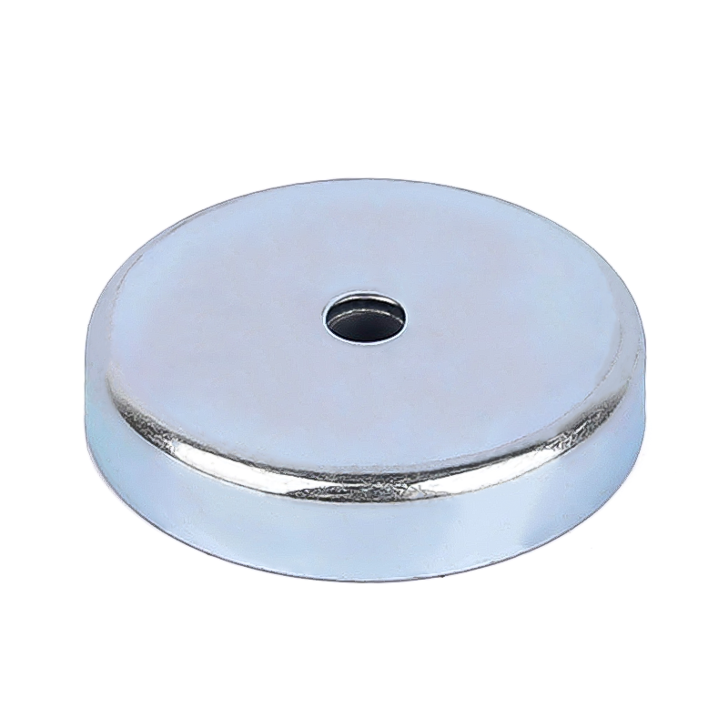
Understanding the structural profile of internal female threads is crucial for proper integration. The internal threaded socket sits completely flush or slightly below the top surface of the steel housing. Manufacturers design the steel cup to surround the magnet completely. This specific geometry centralizes the magnetic field on the active face. It effectively shields the sides and back from emitting stray magnetic fields. The threaded socket allows you to screw a separate threaded bolt directly into the assembly.
You should apply specific criteria when determining if an internal thread suits your project. Consider the following ideal success criteria:
Applications requiring a strictly low-profile installation. They offer minimal vertical protrusion above the mounting surface.
Assemblies needing ultimate flexibility. You retain the ability to choose your exact bolt length. You can also select specific head types like countersunk or hex heads.
Suspended equipment installations. These environments often require swapping out a threaded hook or eyebolt frequently.
However, you must strictly observe several implementation constraints. The most critical risk involves using bolts which are too long. A long bolt will eventually bottom out inside the steel cup. When you apply rotational torque to a bottomed-out bolt, the pressure transfers directly downward. This extreme pressure will easily fracture the brittle internal magnetic material. It destroys the component instantly. You must always calculate thread depth precisely. Ensure you leave adequate clearance at the base of the threaded hole.
External thread designs feature a highly distinct structural profile. They utilize a protruding male threaded stem commonly known as a stud. Manufacturers integrate this stud directly into the top of the steel housing. It forms a single, continuous, solid unit. You do not need a separate bolt to attach it. This integrated design simplifies many hardware requirements.
These units excel in very specific engineering environments. Consider the following ideal success criteria for external studs:
Through-hole mounting scenarios. You simply pass the stud through a sheet metal bracket or an acrylic panel. Then, you secure it firmly using a standard nut and split-ring washer.
Rapid assembly lines. Managing a single integrated part saves considerable time. Production workers do not need to juggle separate bolts and magnets simultaneously.
Blind-hole installations in secondary materials. You can thread the stud directly into a tapped hole in a larger aluminum or plastic fixture.
Implementation constraints revolve heavily around dimensional rigidity. The z-axis dimension remains completely fixed. A stud that is too long often requires physical cutting. Alternatively, you might need to insert multiple washers or spacers to bridge the gap. Conversely, if the stud is too short, you compromise safety immediately. Insufficient thread engagement leads to sudden mechanical failure under heavy stress. You must accurately measure your panel thickness before specifying the stud length.
Engineers often misinterpret magnetic pull force data. Advertised pull force numbers assume ideal conditions. They assume direct, perpendicular traction. They also assume the target material is a thick, perfectly flat steel plate. Real-world conditions rarely match these laboratory parameters. Shear load represents a completely different physical dynamic. It occurs when a magnet slides down a vertical steel surface. Gravity pulls the load parallel to the mounting face. In these cases, holding capacity drops drastically. Shear capacity typically equals only 15% to 20% of the maximum direct pull force.
Dynamic loads heavily affect all threaded connections. Constant machine vibration can slowly loosen the assembly over time. You should proactively incorporate thread-locking fluids. Medium-strength compounds work best for most applications. Mechanical lock washers also help secure the joint permanently. Additionally, we highly recommend rubber-coated variants. Rubber coatings drastically increase surface friction. This increased friction helps prevent unwanted rotation and downward sliding.
Dimensional accuracy remains non-negotiable for tight-fit integrations. You must always verify ISO metric thread standards carefully. Look for exact designations like M3, M4, M6, or M8 before ordering. You must also account for standard steel cup tolerances. A loose thread compromises the entire structural hold. Always demand tight machining tolerances from your supplier.
Force Type | Direction of Applied Load | Expected Holding Capacity | Required Engineering Countermeasures |
|---|---|---|---|
Direct Pull Force | Perpendicular (90° to surface) | 100% of Rated Specification | Ensure flat, thick, clean steel target surface. |
Shear Force (Sliding) | Parallel (0° to surface) | 15% - 20% of Rated Specification | Use rubber coating or install mechanical support ledges. |
Dynamic Vibration | Multi-directional impact | Highly Variable (Prone to loosening) | Apply thread-locking fluid and use mechanical lock washers. |
Choosing the correct magnetic material dictates long-term project success. Neodymium (NdFeB) represents the undisputed industry standard for high-strength requirements. It provides immense holding power within a highly compact footprint. This makes it ideal when physical clearance is strictly limited. It allows you to design smaller, lighter assemblies.
Ferrite (ceramic), however, offers a highly cost-effective alternative. It performs exceptionally well in high-temperature environments where Neodymium fails. Choose Ferrite when physical size restrictions are minimal. It occupies more space but delivers excellent value and thermal stability.
Environmental degradation ruins poorly specified components quickly. Moisture and harsh chemicals degrade raw magnetic materials rapidly. The intended operating environment must dictate your coating requirements. Standard Ni-Cu-Ni (Nickel-Copper-Nickel) plating works exceptionally well for general indoor use. It provides excellent basic corrosion resistance. For harsh outdoor or wet environments, choose rubber-coated options instead. They offer superior surface protection and effectively prevent moisture ingress.
You must strictly observe thermal ceilings. Exceeding maximum operating temperatures causes irreversible magnetic loss. Standard Neodymium grades typically degrade rapidly above 80°C (176°F). Once heat demagnetizes the material, the assembly will not recover its original strength upon cooling. Always verify the specific temperature grade rating.
Calculate the exact spatial limitations and maximum footprint of your assembly area.
Determine the absolute maximum ambient operating temperature the component will face.
Identify any corrosive elements in the environment, including high humidity or chemical exposure.
Select Neodymium for maximum strength in tight spaces, or choose Ferrite for budget-conscious, high-heat applications.
Material Type | Relative Strength | Standard Max Temperature | Cost Profile | Best Application Scenario |
|---|---|---|---|---|
Neodymium (NdFeB) | Extremely High | 80°C / 176°F | Premium | Compact assemblies requiring massive holding power. |
Ferrite (Ceramic) | Moderate | 250°C / 482°F | Economical | Large industrial fixtures exposed to intense heat. |
Engineers often underestimate the mechanical fragility of sintered magnet materials. They mistakenly treat them like solid steel components. Sintered metals inherently lack the elasticity of standard steel. Over-torquing a threaded connection represents a critical and common mistake. Excessive rotational force easily warps the surrounding steel cup. This subtle distortion immediately shatters the brittle magnet secured inside. You should always use a calibrated torque wrench during installation. Establish a strict maximum torque value for your assembly line workers.
Mixing dissimilar metals creates severe long-term problems. This becomes especially problematic in wet or highly humid environments. For example, pairing a stainless steel bolt with a standard zinc-plated housing invites galvanic corrosion. The dissimilar metals react chemically in the presence of moisture. This reaction accelerates rust and causes rapid structural decay. You can easily mitigate this risk. Use insulating nylon washers to separate the metals. Alternatively, ensure complete material compatibility across all fastening hardware.
Never accept vague performance claims from unverified sources. You must implement strict supplier validation protocols. Shortlist only those suppliers who readily provide verifiable holding force graphs. These technical graphs must explicitly account for specific air gaps. They must also show performance drop-offs across varying steel plate thicknesses. Furthermore, demand standard compliance certifications. Ensure all components strictly meet RoHS and REACH regulations before finalizing any volume purchase.
Choosing between an internal and external threaded design ultimately comes down to spatial clearance parameters. You must thoroughly map your mounting access and carefully calculate the primary direction of your applied load. Recognizing the vast difference between direct pull force and shear force prevents catastrophic field failures.
Your next step requires moving beyond theoretical datasheets. We strongly recommend evaluating physical prototypes in your actual application environment. Request detailed dimensional CAD files from a qualified supplier to check for assembly interference. Secure physical samples to test real-world pull forces. Finally, test these assemblies directly against your application-specific surfaces to validate your safety margins thoroughly.
A: We strongly advise against it. Machining generates intense localized heat. This heat easily demagnetizes the internal material permanently. Furthermore, drilling introduces harsh vibrations. These vibrations will likely shatter the highly brittle magnetic core, rendering the component completely useless.
A: Several variables cause underperformance. You might be attaching it to thin target metal, which saturates quickly. Uneven surfaces create detrimental air gaps. Painted coatings act as physical stand-offs, significantly weakening the magnetic field. Finally, you might be applying the force in shear rather than a direct perpendicular pull.
A: Standard mechanical best practices apply here. Ensure the thread engagement equals at least the full diameter of the bolt or stud. However, strictly avoid bottoming out the bolt in internal threaded pots. Bottoming out creates immense pressure that fractures the internal material.
A: Yes, but only with appropriate environmental protection. Raw standard versions will corrode rapidly in the rain. We strongly recommend polyurethane or rubber-coated variants. Alternatively, specify marine-grade stainless steel housings. These specialized designs prevent severe rust and stop the internal magnet from swelling.


